General Assembly Introduction
What is Assembly?
Assembly is a the second level of abstraction between hardware and software. Assembly conforms the operations of an instruction set architecture (ISA) of a given processor. For example:
- x86
- MIPS
- ARM/A32
- Arm64/A64
as well as many more.
This diagram gives a good description of where assembly falls in the computer abstraction hierarchy:
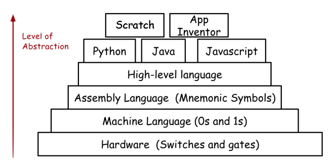
Where the ISA defines what capabilities a processor should have, assembly is a textual implementation of those capabilities that programmers can understand. As an example, consider that many processors need to be able to jump to a new segment of code. Assembly does this with instructions like call (to functions) and jmp (for conditional logic). Don’t worry if this doesn’t make sense right now, as I will go over various common assembly instruction, and their particular implementations in the MIPS ISA.
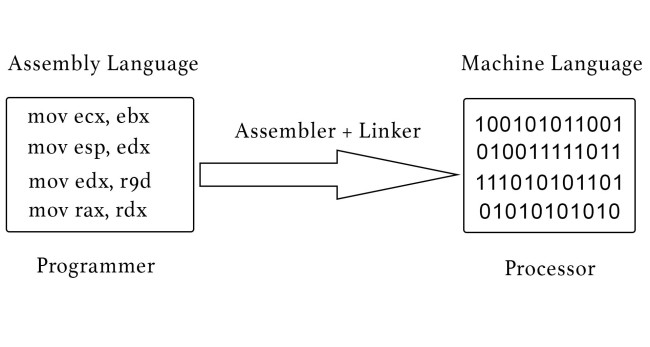
In order for the processor to understand these commands, they must be compiled into a binary format, which can then be sent as electric signals to the processor. The compilation process is determined by the particular ISA in that each command compiles to a fixed length, but can have varying formats.
MIPS Introduction
MIPS Registers
In assembly language, there are placeholders available to store values known as registers. We use these placeholders to maintain constant values, memory addresses, and return values necessary for program execution. The following is known as the MIPS ISA Greensheet. This document includes all the specifications of the language:
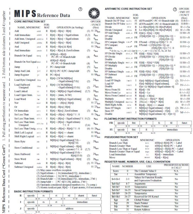
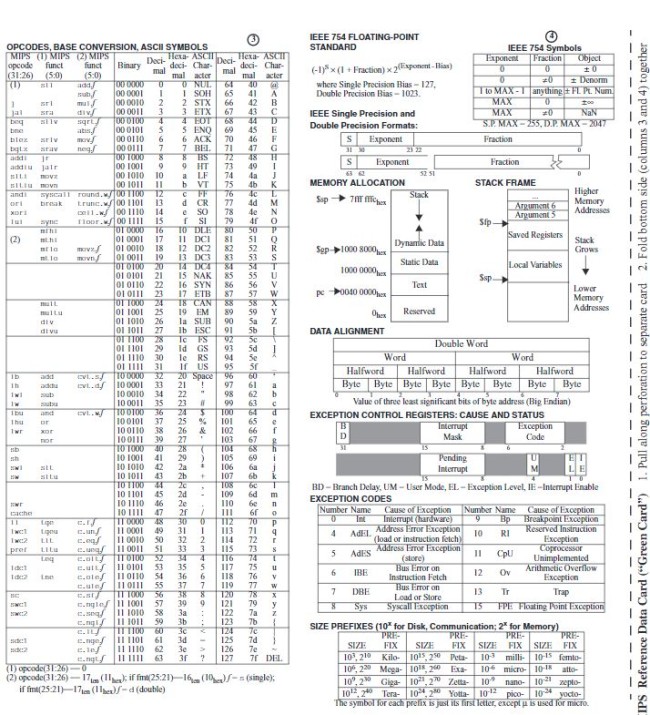
The registers are listed in the lower right-hand corner of the first page. As you can tell, there are 32 registers. Also, all of the register’s names start with a $. I will not explain all of the registers within this article as it has already been documented, but I will touch on some of the important ones. The first register is the $zero register. This register is not to be altered so that it always maintains the value of 0. This might seem useless, but in assembly it is very useful to always have the value 0 available, specifically for conditional logic.
The next register is the $at register. This register is the temporary value holder, and is not preserved across function calls. For example, if you need the value of a numerical operation such as addi to compute something else, but don’t need to maintain that value after the computation has succeeded, you would use $at. Another set of temporary registers with this exact same purpose is $t0-$t9.
The main registers used in MIPS programs are $sp, $fp, and $ra. $sp is the stack pointer, denoting the address of top of the stack. The $fp register is used to maintain the address in memory that the stack frame is at. These are especially useful because they allow the use stack-based memory alignment, which allows for function calling and seperation of memory frames. Finally, the $ra register is used to denote the return address when a function is being call. At the end of every function, to return one simply needs the command jr $ra to go back to the calling function.
MIPS Instructions
There are many different instruction types present in MIPS such as:
* R format (add, addu, etc)
* I format (addi, addiu, etc)
* J format (jmp instructions)
* FR format (floating point arithmetic)
* FI format (conditional branching)
To go over all of the instructions would be a bit tedious as there are many, but everything can be found online. Here are few that you should be familiar with:
add- Adds two registers and stores the result in a register
addi- Adds a register and a sign-extended immediate value and stores the result in a register
beq- Branch to a specified offset if two registers are equal
bne- Branch to a specified offset if two registers are not equal
j- Unconditionally jump to some memory address
jal- Jumps to the calculated address and stores the return address in
$ra
- Jumps to the calculated address and stores the return address in
jr- Jumps to the value of a specified register (typically
$ra)
- Jumps to the value of a specified register (typically
Example
Let’s convert one instruction in MIPS to the equivalent binary code that the processor would see. On the greensheet, you can see many instructions. We are going to convert a simple command, addi $t0, $s0, 1. This command takes the value stored in $s0, adds 1 to it, and then stores the result in $t0. So to convert the command, we simply find the addi instruction on the greensheet.
From this we can see that the format for this instruction is I, the operation equivalent in Verilog is R[rt] = R[rs] + SignExtImm and that the opcode for this instruction is 8. When there is only one entry listed in the opcode/func field, that is the opcode as all instructions must have an opcode. So then the func field is not required. Scrolling down on the greensheet we can see a table for all of the basic instruction formats.
Taking a look at the I format, we can see that an instruction is 32 bits long. It should be noted that all MIPS instructions are 32 bits in length. The first 6 bits are the opcode, the second 5 bits represent rs, and the third set of 5 bits represents rt. The remaining 16 bits are known as the ‘immediate’ field. This field is the constant value that we add to the second argument given, in this case $s0.
In order to translate this instruction into binary, we must have the opcode, rs, rt, and the immediate field and translate each of those to binary. We know that the opcode is 8 in hex, so the corresponding 6 digit binary number would be 001000. R[rt] is simply $t0 which is register 8 (check the register table of the green sheet). R[rs] is $s0 which is register 16. Converting both of these to binary with 5 digits each, we have rt = 01000 and rs = 10000. All thats left now is the SignExtImm immediate field, which is the value 1. 1 in 16 digit binary is simply a 1 preceeded by 15 zeroes. The end command looks like this:
opcode = 001000

rs = 10000

rt = 01000

SignExtImm = 0000000000000001

addi $t0, $s0, 1 = 00100010000010000000000000000001
Conclusion
There is more to be discussed about MIPS programming, which I plan to make articles over as well, including the structure and functionality of the MIPS processor as well as what a typical MIPS assembly program would look like. Also, there are plenty of challenges on a website (shameless plug) called root-me. Consider going there and looking at the MIPS crackmes and system exploitation challenges to increase your understanding in this topic!